アルミ押出プレス
等速押出/等温押出
制御システム
RcdWin
RCDIGITAL,Inc.
November 2022
Download “Constant-Speed and Isothermal Extrusion System 2025 for Aluminum Extrusion Plants” (Right-click → Save link as to download.)
(右クリックー>対象をファイルに保存 で、ダウンロードできます。)
20181205版プログラムの最新情報 等温押出(RcdWin)パンフレットをダウンロードできます。(日本語)
(右クリックー>対象をファイルに保存 で、ダウンロードできます。)
1
高速押出し
1-1高速押出し
ラム速度と設定速度の誤差がゼロになるように制御電圧をフィードバックすれば定速制御が可能です。 ここで、押出機の特性から決定される制御電圧は、フィードフォワードとしてフィードバックから決定される電圧に加えられる。 これにより、ラム速度が速くなります。 このフィードフォワード制御電圧は、オーバーシュートに対する応答制御電圧として使用することができる。
第19章のラム速度立ち上がりの自動調整による最適化で、立ち上がりはさらにに速くなります。
ラム速度立ち上がりの自動調整による最適化
高速押出しの例を図1-2から図1-4に示します。
1-2
押出機の特性
ここで言う押出機の特性とは、押出しの定常状態(ラム速が設定速度を維持している状態)の時のラム速と制御電圧との関係のことです。これは一次式で現すことができます。この関係を有効に利用することにより、立上がりを早くし、オーバーシュートを減少できます。
問題は、この関係が変化するということです。小さな変化(例えば季節的なもの、設備の関連の油圧異常など)に対しては、動的に関係式を補正します。ただ、もしオーバーシュートが目立つ、立上がりが悪い、などの現象が起きるようであれば、関係式を簡単な操作で入れ直すことができます。
通常は、関係式の計算を自動にしておけば問題ないです。RcdWinでは、最新のデータから関係式を計算し、図1-1のように表示する機能を持っています。
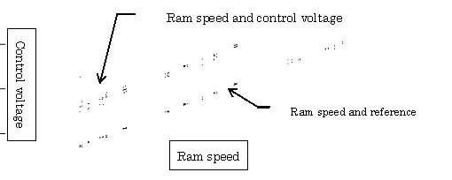
図1-1 押出機の特性のグラフ
Press Machine
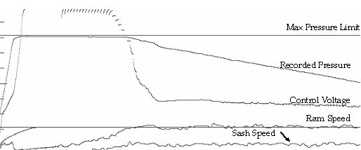
図1-2 フィードフォワードあり 設定速度は 6.2㎜/sec。立ち上がりずらい押出ダイスです。
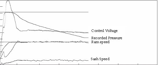
図1-2 フィードフォワードあり 設定速度は 6.2㎜/sec。立ち上がりずらい押出ダイスです。
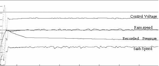
図1-2 フィードフォワードあり 設定速度は 6.2㎜/sec。立ち上がりずらい押出ダイスです。
1-3制御理論
1-3-1ラム-トルク(流量)関係式
定常状態ではラム速と出力トルクが図1-1のように一次式の関係にあります。その関係式を利用して、制御トルク(流量)を予測計算しています。そのため、低速から高速まで、安定した等速制御が行えます。
1-3-2フィードバック+フィードフォワード
下の式により、PIDによるフィードバックと関係式によるフィードフォワードを同時に実行しています。そのため、安定した高速な押出が可能です。
Torque(流量) = Kp×e + Ki ∫edt +Kd de/dt + f(ref)
ここで、
Torque(流量): 制御電圧(トルク)
Kp:比例ゲイン
Ki:積分ゲイン
Kd:微分ゲイン
e:偏差
f():ラム-トルク関係式
ref:設定電圧
1-3-32自由度PID
立ち上がりモードと等速モードを分離してPIDのパラメータを設定できます。
そのため、立ち上がりのオーバーシュートを抑えるために制御ゲインをさげても、等速制御に影響しません。
1-3-4圧力考慮
ラム速が設定速度に到達しても、プレスのメイン圧力がリリーフバルブ設定値により抑えられている状態では定常とはいえません。そのため、圧力も考慮して、立ち上がりモードと等速モードを判定しています。
リリーフバルブが吹いている状態のときは、トルク信号を抑えることにより油圧モータの負荷を低減します。
油圧ポンプは、リリーフバルブが吹いて、高圧力が長く継続すると停止します。
↑TOP of Page
2
オーバーシュート防止
ラム速度の立ち上げのフィードバックゲインと等速でのフィードバックゲインを別にしているので、等速部分とは独立にオーバーシュート防止の調整を行えます。
また、フィードフォワードではラム速の勾配、誤差、押出機の特性を考慮して、オーバーシュートが起きないようにまたハンチングを防止して制御信号を計算しています。
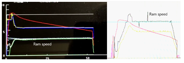
左側がRcdWinの等速押出、右側がPIDの等速押出です。
RcdWinはオーバーシュートしませんが、PIDは大きくオーバーシュートします。
左側がRcdWinの等速押出、右側がPIDの等速押出です。
RcdWinはオーバーシュートしませんが、PIDは大きくオーバーシュートします。
↑TOP of Page
3
省エネルギー
ラム速度が上昇するに伴い必要以上の制御電圧をかけても、無効流量となり、油温上昇、電力の損失につながります。これを防止するため、ラム速度と圧力の関係から、制御電圧が必要以上に大きくなるのを防止します。
過負荷状態が長く継続すると、油圧ポンプは停止します。
↑TOP of Page
4
圧力制限
プレスの圧力が圧力制限値をなるべく越えないように制御します。この値は、コンピュータのキーボードから、対話形式で設定できます。
次のような目的に効果があります。
- 油圧ポンプが過負荷で、停止しないようにする。
- モーター負荷の軽減。
- 電力の節減。
- リリーフから逃げてゆく無効流量の防止。
- 油温の上昇の防止。
- 機器、押出ダイス、マンドレルへの圧力負荷を軽減するために、圧力が制限値に達すると同時に下げることもできます。
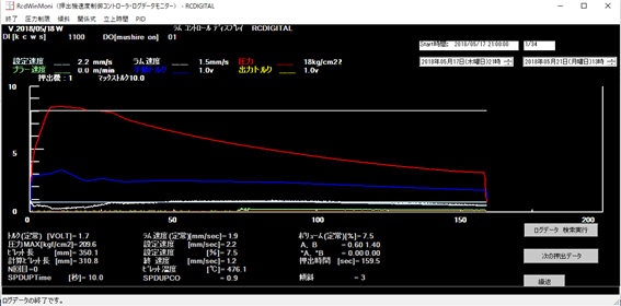
図4-1 圧力制限と傾斜押しの例 設定速度は 2.2㎜/sec。
説明>圧力がリリーフバルブ値をオーバーしているため、トルク(流量)を下げています。後半は、製品温度が上昇して不良にならないように、ラム速度を傾斜させています。
↑TOP of Page
5
傾斜押し
ビレットの後半部分になると、材質によっては、速度を傾斜させます。製品の温度が上がらないようにするためです。RcdWinは図5-1のような傾斜パターンを設定できます。
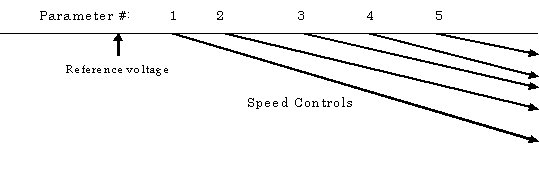
図5-1 傾斜押しのパターン
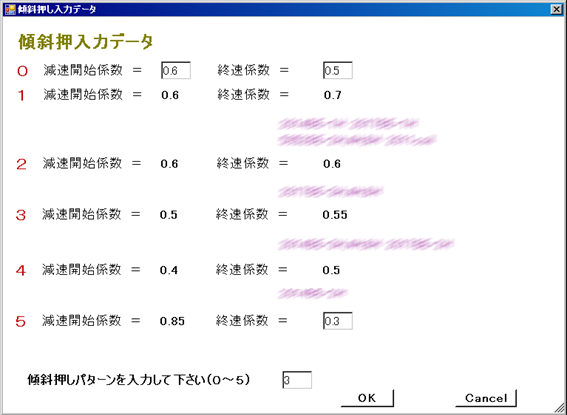
図5-2 パラメータ入力画面
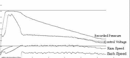
図5-3 傾斜押し 設定速度は 6.1㎜/sec 終速度 5mm/sec。

図5-4 傾斜押し 設定速度は 9.7㎜/sec 終速度 5.4mm/sec。
↑TOP of Page
6
制御画面
RcdWinで制御を行っているときには、ディスプレイに次の図のような画面が表示されます。
中央にあるグラフの表示は押出時の制御状況を表示します。
その他のグラフの外にある数値等の表示は押出が終わった時の計測データと制御パラメータの表示です。
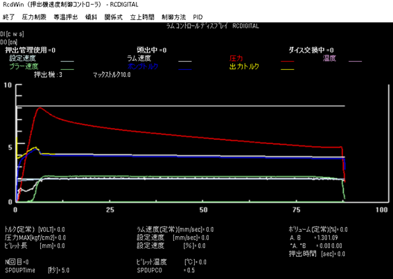
図8-1 RcdWinの制御画面
↑TOP of Page
7
押出データ検索
RcdWinMoniは日付と時間を指定して検索し、 rcdWinが登録した20,000件の押出データを表示します。
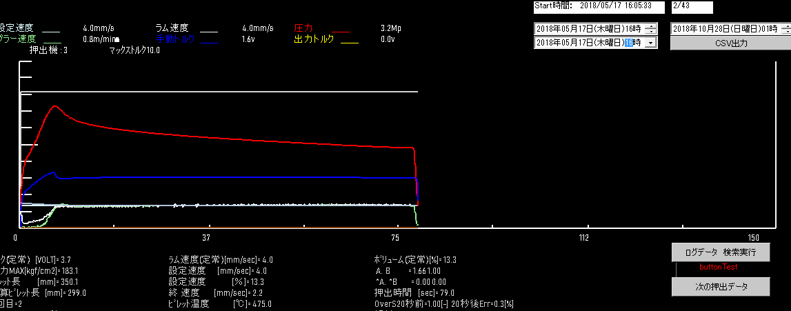
図9-1 RcdWinMoniの制御画面
RcdWinMoniは日付と時間を指定して検索し、 rcdWinが登録した20,000件の押出データを表示します。
ラム速データのスペクトル解析
↑TOP of Page
8
リモートメンテナンス
インターネットを利用してプログラムをインストール、制御パラメータの調整、プログラムのメンテナンスを行います。
リモートサポート(ここをクリック)。
- リモートアクセスのソフトTeamViewerQA.exeを使用して、リモートでプログラムをインストールします。
- 制御パラメータ調整中は、リモート監視用のソフトTeamViewer Host.exeをインストールします。24時間監視が可能になります。
- 押出の調査依頼時に、等速押出しパソコンにログインして、押出データを調査致します。
- 等速押出パソコンには、過去の押出状況が再現できるように、データがログされています。
- 調査時には、ローカルなネットワークをインターネットのネットワークに接続する必要があります。
- これは、ローカルネットワーク用のハブに、インターネットのLANケーブルを差しこんで行います。
- リモートメンテナンスは、日本だけでなく、韓国、中国の工場に対しても行っています。
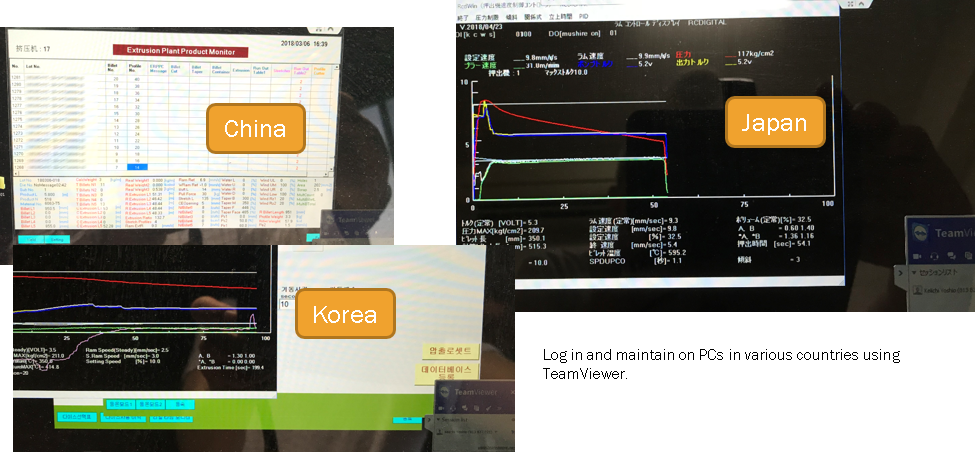
図10-1説明>TeamViewerを使用して、3か国でリモートメンテナンスしています
↑TOP of Page
9
パソコン画面
- 等速(RcdWind)、押出管理(EM)、押出データ解析(EDA)など、たくさんのプログラムが稼働します。
- そのため、ディスプレイは大きな27インチWQHDの使用がいいと思います。
- 防塵パソコンラックは、27インチWQHDディスレイの全部を見ることができるものが必要です。例えば、まもる君Light48パソコンラックは27インチディスプレイを見ることが可能です。
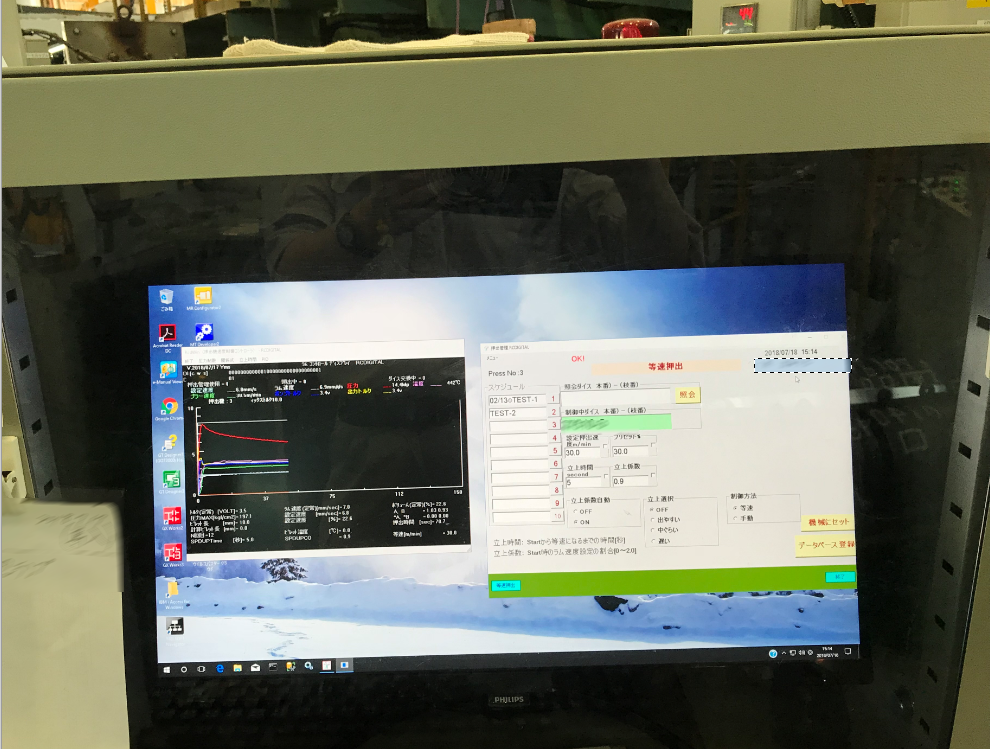
図11-1 等速押出(RcdWin)と押出管理(EM)
↑TOP of Page
10
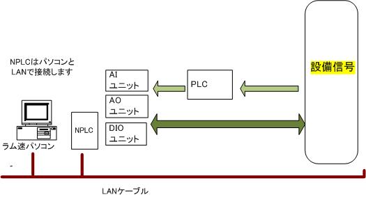
PCとネットワークPLCの分散制御
アルミ押出機のパソコン制御が、LANに接続したPCとネットワークPLCを使用して分散制御ができるようになりました。
PCの役割は押出機の制御ロジックの実行です。ネットワークPLCの役割は設備との信号のやり取りです。
分散制御によるPCのメリットは以下です
- PCはPLCとLANケーブルで接続しているだけです。そのため、工場内のどこにでも置くことができます。
- 過電圧の心配がなく、電気的に安全です。
- 工場の設備管理者が苦手なPCの計測ボードをメンテする必要がありません。
分散制御によるPLCのメリットは以下です。
- 対環境性がすぐれているので、機械やセンサーのすぐそばに置くことができます。
- 単位の変換など、単純ロジックはPLCが行います。
- PLCネットワークは、プログラムが必要なく設定だけで行えます。データ送受信が簡単です。
- 工場の設備担当者はPLCの扱いに慣れています。
PCは計算やデータベースなど得意な分野の仕事に集中できるようになります。PLCは設備との信号のやり取りが主体ですが、簡単な制御ロジックを組み込むことも可能です。
注>ネットワークPLC: Ethernet機能付きPLC(Programable Logic Controller )。リレー回路の代替装置として開発された、手のひらにのる小さなコンピュータです。工場の自動機械のシーケンス制御に使用されます。
15-1 パソコンとネットワークPLCの分散制御図
↑TOP of Page
11
アルミ押出しのリアルタイムモニタ
押出データ解析(EDA)の1画面として、リアルタイムモニタを作りました。
押出1個ずつ表示するのではなく、複数の押出を連続して表示します。
EDAは、RcdWindと違って、複数のパソコンにインストールすることができます。
EDAは、押出ダイス単位に、以前どのような速度で押出をしたかの履歴をみるもできます。
作業者にとって、便利なツールです。
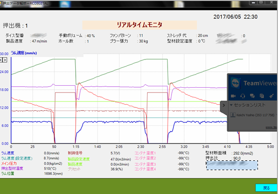
図17-1 押出データ解析(EDA)の一部の画面。複数のパソコンにインストールできます。
↑TOP of Page
12
ラム速データのスペクトル解析
RcdWinMoniプログラムで出力した等速押出12.7[mm/s], 等速押出1.9[mm/s] のCSVファイルに対して、スペクトル解析を行ってみました。
ラム速度が遅いと、振動の周期が早くなり、振幅も大きくなることが分かりました。
ラム速が早いと、±0.10[mm/s]で振動、周期は、約1秒。
ラム速が遅いと、±0.15[mm/s]で振動、周期は、約0.5秒。
定期的に解析を実施することにより、機械のメンテナンスに役立ちます。
不良発生時の解析データとして役立ちます。
18-3にべつの工場のラム速データのスペクトル解析を載せます。機械によりラム速データが異なることがわかります。
18-1 等速押出12.7[mm/s]のスペクトル解析
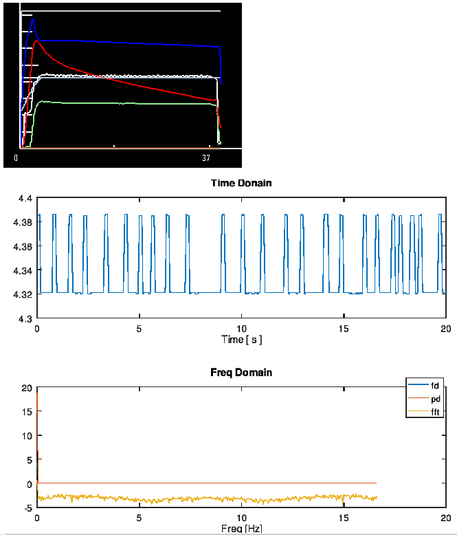
図18-1 スペクトルには3個山があります。ラム速は、4.39[V]-4.32[V]=0.07[V]±0.035[V]で振動(±0.105[mm/s])で振動周期は、約1秒です。
18-2 等速押出1.9[mm/s]のスペクトル解析
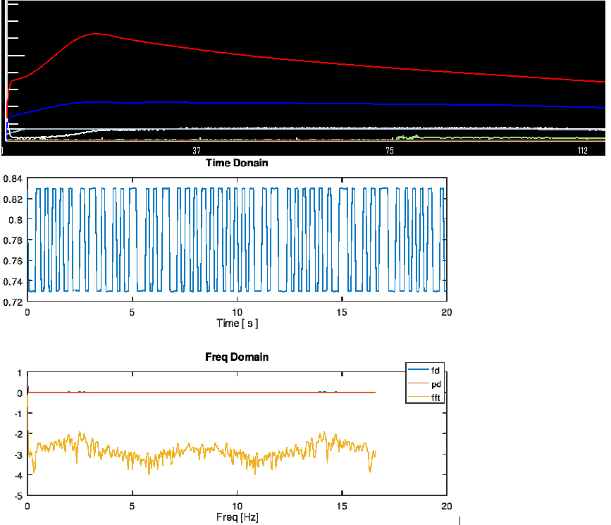
図18-2 スペクトルには3個山があります。ラム速は、0.83[V]-0.73[V]=0.1[V]±0.05で振動(±0.15[mm/s])で振動
周期は、約0.5秒
18-3 別工場の等速1.9[mm/s]のスペクトル解析
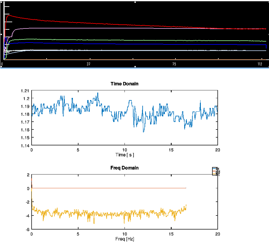
図18-4 スペクトルには山がありません。ラム速は、1.16[V]-1.19[V]=0.03[V]±0.015で振動(±0.045[mm/s])
↑TOP of Page
13
ラム速度立ち上がりの自動調整による最適化
等速押出の最大の目標は、オーバーシュートしないで、なるべく早く立ち上げることです。
パラメータには立上係数と立上時間があります。それらをを最適化しました。
19-1 オーバーシュートした時の自動調整
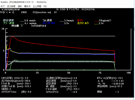
Fig. 19-1 Description> Set speed 5.9 [mm / sec] Overshooting occurred with a rising coefficient of 1.0. Therefore, the coefficient is 0.9.
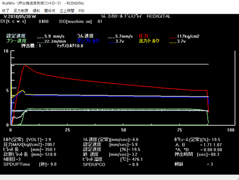
図19-2 説明>設定速度5.9[mm/sec] 立上係数0.9で押出しをして、問題ないので係数が0.9のままです。。
19-2 立上がりが遅い時の自動調整
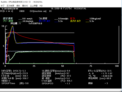
図19-3 設定速度9.7[mm/sec] 立上係数1.0で押出しをして、9秒で等速にならないので、係数が1.1になりました。
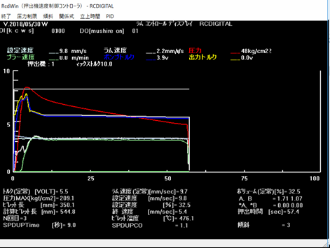
図19-4 設定速度9.7[mm/sec] 立上係数1.1で押出しをして、問題ないので係数が1.1のままです。
↑TOP of Page
14
ラムスピードの立ち上がり時間の自動化
”19 ラム速立上の自動調整による最適化”では、立上係数の説明をしました。ここでは、立上時間の説明をします。
20-1 立上時間自動化の動作
立上係数の自動化は、立上時間より遅く立ち上がる押出ダイスに対しては、早く立ち上げます。しかし、立上時間より早く立ち上げる押出ダイスに対しては、遅く立ち上げます。
このデメリットを改善するために、立上時間の自動化を使用します。
立上係数が変化しない時に、オーバーシュートしていなければ、立上時間を短くします。逆に、オーバーシュートしていれば、長くします。
立上係数が変化しない回数は、2回と設定すれば、3回目からは立上時間が変化します。
20-2 立上時間短縮の効果の計算
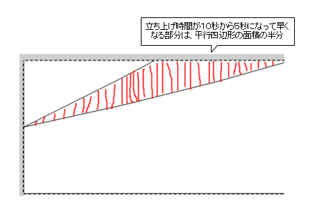
説明>立上時間を短くすることによる押出時間の短縮は平行四辺形の面積。
立上係数と立上時間を以下と仮定する。
立上時間を10秒から5秒にする場合。
立上係数 0.5秒
立上時間 10秒
立上係数 0.5秒
立上時間 5秒
ラム速設定が、6[mm/s]の時は、押出時間は速度×時間の面積なので、平行四辺形の面積を計算して、2で割ります。
立上係数 が0.5なので、設定速度6[mm/s]を2で割ります。立上時間の差は5「s」なので、5を掛けます。
(6[mm/s]/2*5[s])*0.5 = 7.5[s]
7.5秒押出時間が短縮します。
立上時間を短くする効果は、ラム速度設定に比例して大きくなります。
4[mm/s]の時は、5秒早くなります。
10[mm/s]の時は、12.5秒早くなります。
↑TOP of Page
15
円管パイプ2孔の等速押出
円管パイプ2孔の押出は難しいと押出作業者に言われました。日本にある産業用押出材を生産している工場で20年以上実績のある圧力制限という手法で、問題なく等速押出ができました。押出作業者も等速押出により、作業が楽になるので喜んでいました。
押出速度の設定で、[機械にセット]が面倒くさいと言われたので、[+0.1]ボタンなどですぐに速度が変わるようにしました。これも、押出作業者が喜んでいました。
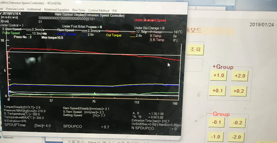
図21-1 説明>円管パイプ2孔の等速押出の押出速度の自動設定
↑TOP of Page
16
低速等速押出
産業用押出材は、1[mm/s]ぐらいの低速押出が多いです。この例では、圧力は210[kg/cm2]を超えていません。高圧ダイスといって210[kg/cm2]を長く継続するものもあります。
等速押出の設定は、1.5[mm/s]ですが、手動押出の場合は、1.2[mm/s]ぐらいにするようです。手動の場合は、後半で0.3~0.4[mm/s]上昇するからです。
この例では、押出時間は386秒ですが、500秒以上のものもたくさんあります。手動押出に比べて、等速押出の設定速度を0.4[mm/s]ぐらい早くします。その場合、0.4*500 = 200秒押出時間が短縮されます。
立上係数は、自動調整されます。トルク(流量)が大きくなっていますが、ラム速度を早く立ち上げるためです。
ラム速度センサは位置センサです。図19-1は、速度センサです。位置センサで等速押出をすると、プラー速度が傾斜する傾向にあることが分かります。
製品が不良になる原因の一つは、後半で温度が上昇するためです。プラー速度が傾斜する傾向になると、後半の温度上昇が防止できます。
位置センサによる等速押出は難しいです。他の会社はやりません。ただし、温度上昇防止の利点は、日本語の諺にある不幸中の幸い(It was hard, but there is an advantage)かもしれません。
PIDのパラメータを高速押出と低速押出に2分割しました。かなり違うようなので、2分割は良かった思います。調整も楽になりました。
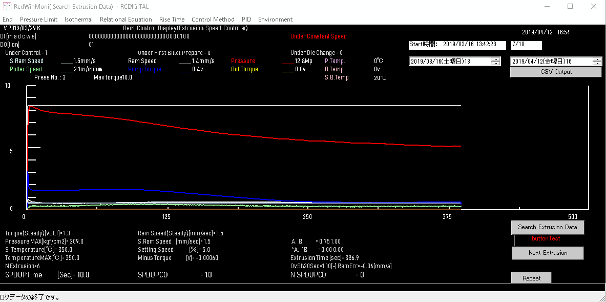
図22-1 説明>位置センサによる1.5[mm/s]等速押出
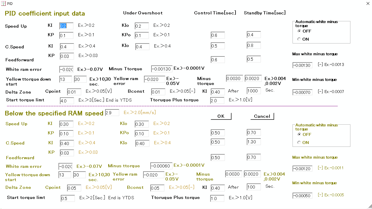
図22-2 説明>2分割したPIDパラメータ入力画面
↑TOP of Page
17
RcdWin制御パラメータの多言語対応
Languageのリストボックスで、言語を選択できます。現在は、英語、日本語、韓国語、中国語の言語リソースファイルを作りました。
他の言語のリソールファイルも作成する予定です。グーグルで翻訳するだけなので、それ程の手間ではありません。
このEnvironment画面のパラメータも新たに作成しました。メニューバーのEnvironment->Environment1で表示できます。
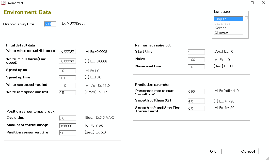
図23-1説明>英語のEnvironment Data画面
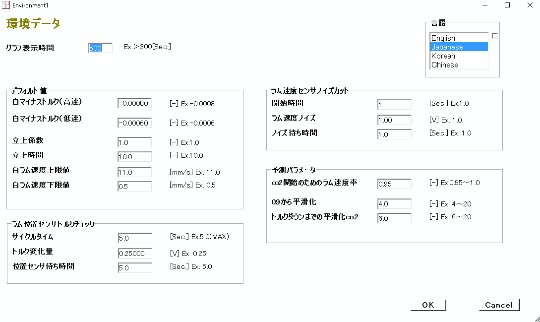
図23-2説明>日本語のEnvironment Data画面
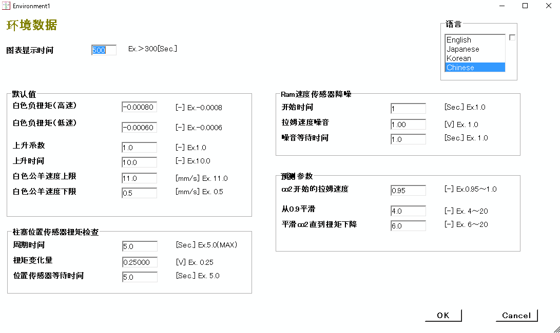
図23-3説明>中国語のEnvironment Data画面
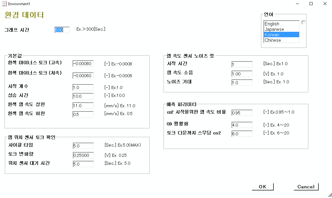
図23-4説明>韓国語のEnvironment Data画面
↑TOP of Page
18
インターフェイスPLCのインターフェイスデータとPLCパラメータデータの入力画面
設備の機械とのデータの交換が簡単に行えるように、Plc Interface Data画面を作りました。
RcdWinはPLCとデータのやり取りをして等速押出を行います。図24-1の例だと、PLCのデバイスのD100~D126を使用します。データのスケールをここで調整します。
RC Digitalはリモートで或いは工場に行って、プログラムをパソコンにインストールします。
ただし、1から12番までのデータは工場で用意する必要があります。13~16はRcdWinの出力なので、これを設備の機械に接続する必要があります。これも、工場が行う必要があります。
工場で難しい場合は、専門の設備改造業会社に依頼すると良いです。
等速押出に最小限必要なデータは、1,2,5,6,7,11,13,16だけです。
図24-3に、工場のLANの配線を書きました。 Rc Digitalは、リモートでプログラムをインストールして、プログラムのパラメータを調整します。
工場或いは専門の設備改造業会社はパソコンとInterface PLCを用意します。そして、Interface PLCと機械のPLCを接続して、データの送受信を確認します。
設備の改造方法の詳細は、メールでお問い合わせ下さい。
プログラムはリモートでメンテナンスできます。ただ、機械のメンテナンスや電気工事などは、リモートではできません。専門の設備改造会社を利用する場合は、工場の近くの会社を選択するのがよいと思います。
図24-2は、PLCデータを設定する画面です。PLCのメーカー型式、IPアドレスやポートなどです。PLCの型式は、三菱のQ03UDE CPUです。実績があるのは、三菱、オムロン、シーメンスです。その他のPLCについては、お問い合わせ下さい。
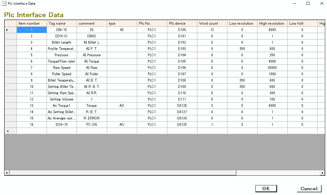
図24-1説明>PLCとのインターフェイスデータ
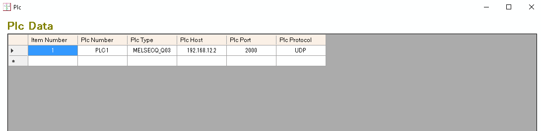
図24-2説明>PLCデータ
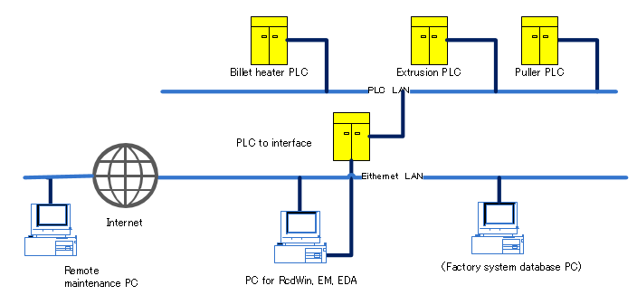
図24-3説明>リモートメンテナンスパソコンとRcdWinパソコンとインターフェイスPLCと工場機械の複数PLC
↑TOP of Page