ビレットテーパーと定常温度による等温押出
RCDIGITAL.CO.JP
November 2022
1
はじめに
ビレットテーパーとRcdWinによる等速押出による等温押出データを使用します。定常状態温度による等温押出の手法で、制御信号がどうなるかシミュレーションしました。予想としては、計測データの制御信号に比べて、シミュレーションの制御信号が、押出の後半部分で下がる筈です。理由は、押出形材温度は、後半で上がるからです。
前半で、シミュレーションと計測データがいくらか一致しないのは、両方のパラメータが少し違うからです。シミュレーションでは、定常温度を見つけて、シミュレーションの制御信号をチェックします。
プログラムはRcdWinのデータのシミュレーション用のプログラムRcdWinMoniです。
↑TOP of Page
2
ビレットテーパーとは
ビレットテーパーはビレットヒータの一種です。ビレットの先端からビレットの後端に温度勾配を付けます。例えば、ビレットの先端を500度℃にして、後端を470℃にすると、30℃の温度勾配ができます。
等速押出で速度を一定にしても、押出ダイスや合金より、押出温度が上昇することがあります。それを避けるため、ビレットの温度に勾配をつければ、押出温度が一定になるかもしれないという考え方です。
ビレットヒーターには、ガス加熱炉式、電磁誘導加熱式、強磁場加熱式などがあります。
・ガス加熱炉式というのは、10m位の長さがある長尺ビレットに使用されます。ビレットテーパーに送るまえに、400℃ぐらいに加熱します。長尺ビレットは、1mぐらいの長さに切断されてから、ビレットテーパーに送られます。
・電磁誘導加熱式は、1mぐらいに切断されたビレットに温度の勾配をつけるために使用されます。ビレットテーパーを4つのゾーンに分けて、ゾーンごとにコイルを配置します。各コイルにながれる周波数や電圧を変更すると、磁力線によりできる渦電流の大きさが変わり、温度勾配ができます。100秒ぐらいでテーパー加熱が終了します。
システム効率は60%ぐらい。
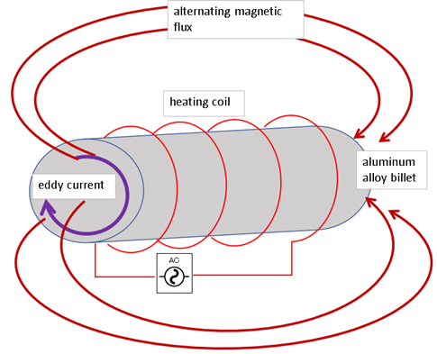
FIG2-1> 誘導加熱
コイルに電流を流すと、磁力線が発生します。コイルの中にアルミニウム合金を入れると、アルミニウム合金内に磁束の変化を妨げる方向にうず電流が発生します。電気抵抗により W=i^2×Rに相当するジュール熱が発生して金属が加熱します。
W ∝fB/σ W: 加熱電力 f:周波数 B:磁束密度 σ: 導電率。
・強磁場加熱式は、超電導磁石に囲まれたビレットを回転させてできる渦電流で加熱します。電磁誘導加熱式に比べて、ビレットを4Hzぐらいでゆっくり回転させるので、渦電流がビレット中心まで均一に流れます。そのため、表面から中心まで温度が均一になります。
テーパーの調整は、ゾーンごとの超電導磁石の角度で行います。角度を傾けると、磁場が弱くなるので、渦電流も弱くなります。
電磁誘導加熱に比べて省エネルギーで、システム効率は80%ぐらいと言われています。
注>アルミ合金ビレットとは
製品に必要な特性を得るため、アルミニウムにマグネシウム、シリコンなどを混ぜて、鋳造機で作成した10mぐらいの円形状の合金です。
アルミニウムの原料はボーキサイトという鉄鉱石です。ボーキサイトから電気分解してアルミニウムを取り出す工程を製錬といいます。
↑TOP of Page
3
放射温度計とは
工場で使用する温度計には、熱電対、測温抵抗体、放射温度計などがあります。
アルミ押出中の押出形材の温度は、動いているものを非接触で、高速に計測できる放射温度計を使用します。
放射温度計は、サーマパイル検出素子で形材の赤外線を電気信号に変換します。
この電気信号を増幅し、放射率補正をおこなって温度を出力します。
放射温度計のパラメータは、押出形材の放射率、押出形材とセンサとの距離、押出形材の測定できる範囲(スポット径)の3パラメータです。
3つのパラメータは、押出の現場では、正確に設定することは難しいです。
理由は以下です。
・放射率は押出形材のアルミ合金ごとに異なります。アルミ合金ごとに、放射率調べて設定することは、作業効率が悪いです。
・押出形材は、押出ダイスごとに形が異なります。そのため、押出形材とセンサとの距離が金型毎に異なります。それを、調べて設定することは、作業効率が悪いです。
・押出形材とセンサとの距離は大きくなりがちです。押出形材の温度は高温で550℃ぐらいになります。そのため、距離を小さくするとセンサが壊れる可能性があります。
しかし、距離が大きくなると、スポット径が大きくなります。スポット径が押出形材の面がより大きくなった場合、正確な放射を計測できなくなります。
以上の理由で、アルミ押出形材の放射温度は、正確な値というよりだいたいの温度の目安です。
重要なのは、温度勾配です。
温度が上昇すれことが分かれば、押出速度やビレットテーパーで調節できます。放射温度計の温度を見ると、温度勾配は正しく計測されているようです。
注>放射率とは
放射率は0から1の値です。
1=吸収率+反射率+透過率です。
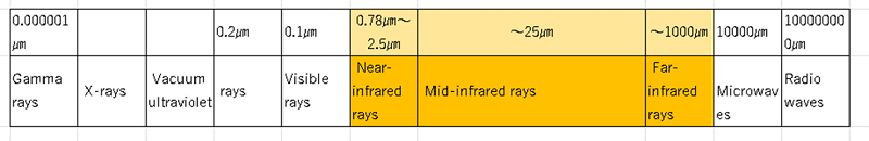
放射率=吸収率です。アルミ合金の場合、赤外線の波長により異なります。
高温で使用される近赤外線の場合は 0.1とか0.2位の値です。
近赤外線は、エネルギーが大きく、波長が小さいので、安定で小さいスポットにできます。
注>熱電対とは
熱電対はゼーベック効果を使用する。
2種類の金属の接合部(測温接点)T1の温度と計測器側接点(基準接点)T0の温度差Tの電圧により、温度情報が電気信号(熱起電力)として検出される。
注>測温抵抗体とは
金属または金属酸化物が温度変化による電気抵抗値を測定することで温度を測定するセンサです。
ごく低温は測定できるが、高温はできない。環境の温度測定には測温抵抗体、工業炉の温度測定には熱電対が使用される。
↑TOP of Page
4
等温押出の調整とは
等温押出の調整としては、以下の3点が考えられます。
(1) 定常状態前の立ち上げの温度をもっと高くする。
(2) 押出温度に余裕がありそうなので、押出速度を上げる。
(3) 等温押出の精度を上げる。
(1) に対しては、オーバーシュートしない範囲で、RcdWinの立ち上げ係数を調整することにより実現できます。
(2) に対しては、設定押出速度を上げることで実現できます。押出ダイスやビレットののアルミ合金の種類により異なりますが、例えば、押出速度 4mm/sの時の定常温度は 564℃、 5.5mm/sの時は 577℃です。スピードが高いと定常温度も上がる傾向があります。
(3) これから、説明する定常温度の等温押出です。
4-1 定常温度の等温押出の調整
ビレット温度(或いはビレットテーパー温度)と押出速度は、通常指示書にあります。
しかし、押出形材温度は通常ありません。
そのため、押出速度から押出温度を自動で求めるようにしました。
押出速度が設定速度になり、形材温度が安定した時の温度を、定常温度といいます。作業者は、等速押出をしながら、自動で等温押出ができるようになりました。
ビレットテーパーは、必ず押出機に付属しているわけではありません。定常温度による等温押出を使用すれば、速度が傾斜して遅くなりますが、等温効果を期待できます。
ビレットテーパーがある時でも、等温の微調整をするのでメリットはあります。
例>
・定常温度より1℃以上より形材温度が上昇した場合は、設定速度の10%まで傾斜する。
・押出の中断でビレットが冷えた時でも、等温効果が期待できます。
注意点>
・形材温度は非常に不安定です。安定しない時は、自動で等速押出をします。
・形材温度は押出ダイスにより異なり、取得できる時とできない場合があります。
・定常温度は取得できる時とできない場合があります。
↑TOP of Page
5
定常温度の等温押出のメリット
形材温度というパラメータが増えたことにより、押出の調整幅が広がります。
例えば、以下です。
・ビレットテーパーと放射温度計を設置して、等速押出をすれば、等温押出ができる。作業者の新たな負担がない。
・押出形材の割れなどの不良が出た場合に、形材押出温度も、原因究明のデータとなる。
・定常温度が低いと感じた作業者は、押出速度を上げ、生産性を上げることができます。
・ビレットテーパーの先端温度を上げて、立ち上がりを早くして、生産性を上げることができます。
・等温押出は、一般的に、形材内部のアルミ合金分子配列が均一になり、品質が向上すると言われています。
↑TOP of Page
6
定常温度の探索例
ビレットテーパーとRcdWinによる等速押出による等温押出データを使用します。
定常状態温度による等温押出の手法で、制御信号がどうなるかシミュレーションしました。
予想としては、計測データの制御信号に比べて、シミュレーションの制御信号が、押出の後半部分で下がる筈です。理由は、押出形材温度は、後半で上がるからです。
前半で、シミュレーションと計測データがいくらか一致しないのは、両方のパラメータが少し違うからです。
シミュレーションでは、定常温度を見つけて、シミュレーションの制御信号をチェックします。
プログラムはRcdWinのデータのシミュレーション用のプログラムRcdWinMoniです。
6-1 4例の設定速度と定常温度
| 金型 |
設定速度 |
定常温度 |
押出形材
最終温度 |
温度誤差 |
押出時間 |
備考 |
| A |
4mm/s
|
554℃ |
556℃ |
2℃ |
240seconds |
|
| B |
4mm/s
|
565℃ |
568℃ |
3℃ |
186seconds |
|
| C |
3.5mm/s
|
539℃ |
541℃ |
2℃ |
155seconds |
|
| D |
1mm/s
|
490℃ |
484℃ |
-6℃ |
620seconds |
温度が上昇していないので、普通の等速押出をします。 |
表6-1 設定速度と定常温度
以上の例から、定常温度は500℃以上で探索して、定常温度の等温押出を行えばよさそうです。
注意が必要なのは、何分もリリーフ圧力が原因でラム速度が上昇しない。かつ等速状態が短いと、定常温度が探索できないまま、押出が終了することがあります。
6.2 等温押出グラフ例
| 分類 |
色 |
説明 |
| 設定パラメータ |
水色 |
設定速度 |
| 画面上部の白 |
リリーフ圧力 |
| 定常温度 |
紫の上の黄色 |
定常温度で傾斜押出中 |
| 紫の上のピンク |
定常温度で等速押出中 |
| 計測データ |
紫 |
放射温度計の温度 |
| 赤 |
圧力 |
| 青 |
押出機への制御信号の計測データ |
| 白 |
ラム速度 |
| 緑 |
押出形材速度 |
| シミュレーション |
黄色と白 |
押出機への制御信号のシミュレーション |
表6-2 グラフ線の説明
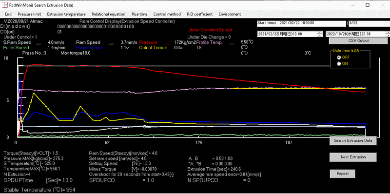
図6-1>金型A
形材温度がほとんど定常温度と同じです。数字上は、2℃上昇していますが、グラフ上はほとんど同じです。
青の制御信号と白のシミュレーションの制御信号の傾きはほぼ同じです。
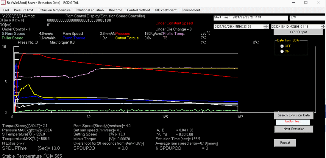
図6-2>金型B
形材温度が、3℃ほど定常温度より上昇しています。
青の制御信号に比べて白のシミュレーションの制御信号がかなり傾斜しています。これは、誤差が大きいからです。
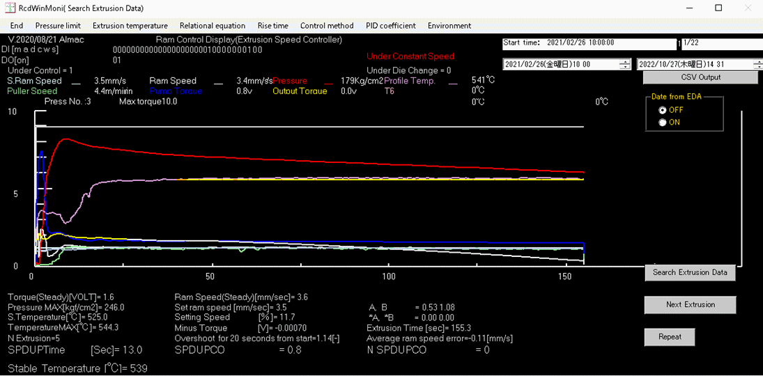
図6-3>金型C
形材温度が、2℃ほど定常温度より上昇しています。
青の制御信号に比べて白のシミュレーションの制御信号がかなり傾斜しています。
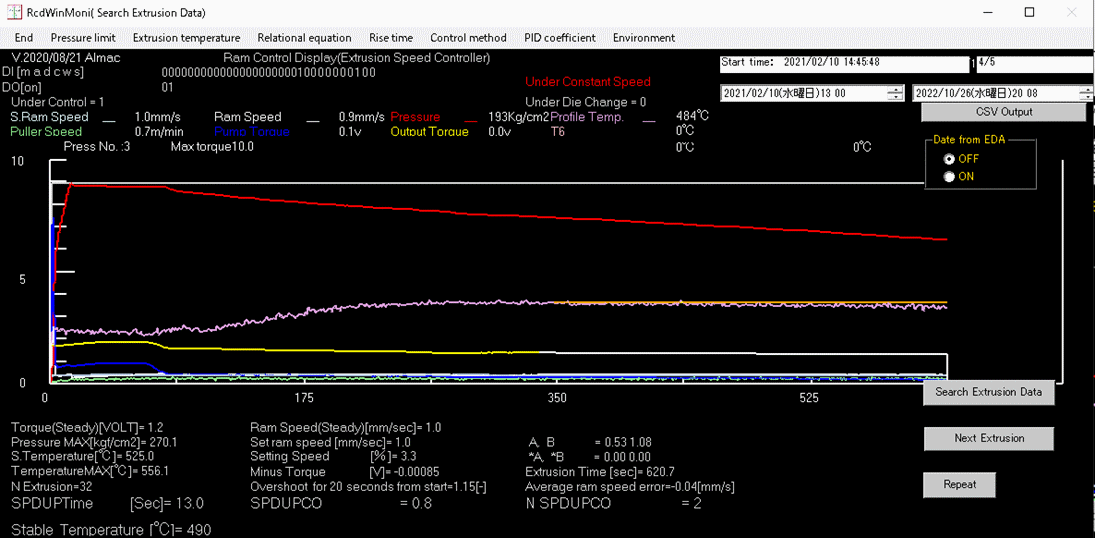
図6-4>金型D
形材温度が、後半で上昇しないで少し下降しています。
青の制御信号と白のシミュレーションの制御信号の傾きはほぼ同じです。
↑TOP of Page