OPC UAと工場のLAN
RCDIGITAL.CO.JP
July 2022
1
はじめに
パソコンには標準Ethernetのソケットが付いています。工場で使用するPLCには標準Ethernet或いは産業用Ethernetのソケットが付くようになりました。工場のLANで使用するEthernetは産業用Ethernetといいます。
例えば、産業用EithernetであるPROFINETを使用すると、オフィスのLANと同じRJ45のケーブルを使用できます。PROFINETのスイッチングハブに、パソコンのLANケーブルを接続できます。PROFINETは、オフィスのLANと同じEthernetベースの技術であり、標準Ethernet上で動作します。
OPC UAクライアントのパソコンとOPC UAサーバーのPLCは、標準EthernetとOPC UAでデータの相互交換ができます。
OPC UAサーバーのPLCは、例えば、PROFINETで工場LAN内のPLC、タッチパネルとデータの相互交換ができます。
従って、OPC_UA サーバーを経由して、パソコンは工場内のPLC、タッチパネルとデータの交換ができます。
素材が製品となる過程は、機械の入力と出力の連結です。
工場の機械はPLCとタッチパネルを利用して制御されています。
工場のLANでは、これらのPLCとタッチパネルがLANで接続されています。
パソコンは工場内のPLC、タッチパネルとデータ交換できます。
そのため、機械やタッチパネルにパラメータをセットしたり、機械を直接制御したりして、工場を自動化し、省力化できます。
自動化は、以下の意味で使用しています。
・素材が製品になる過程をモニタします。
・各機械に人に代わってパラメータをセットします。
(ただし、PLCプログラムの機能追加として、制御信号をセットして、PLCに変わりパソコンで機械を制御することもできます。例えば、RcdWinの等速押出のような機能のことです。)
・生産した製品のロットの歩留まりをリアルタイムで計算します。
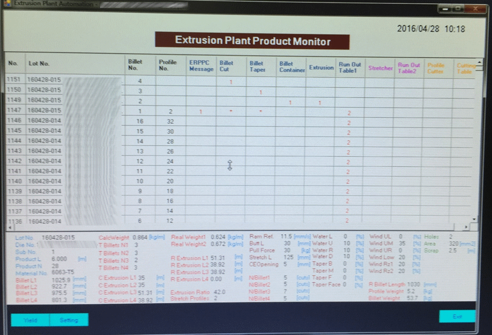
図1-1>アルミ押出工場の自動化の例
・長尺ビレットから押出形材製品ができるまでを表形式でモニタして、機械にパラメータを設定します。
・金型交換が履歴にあるEPの画面。
・No.1147でLot No.が変わりました。製品の断面、長さ、本数などが変更されました。押出が終了したLotが異なる押出形材は、Run Out Table1で、ストレッチを待っています。
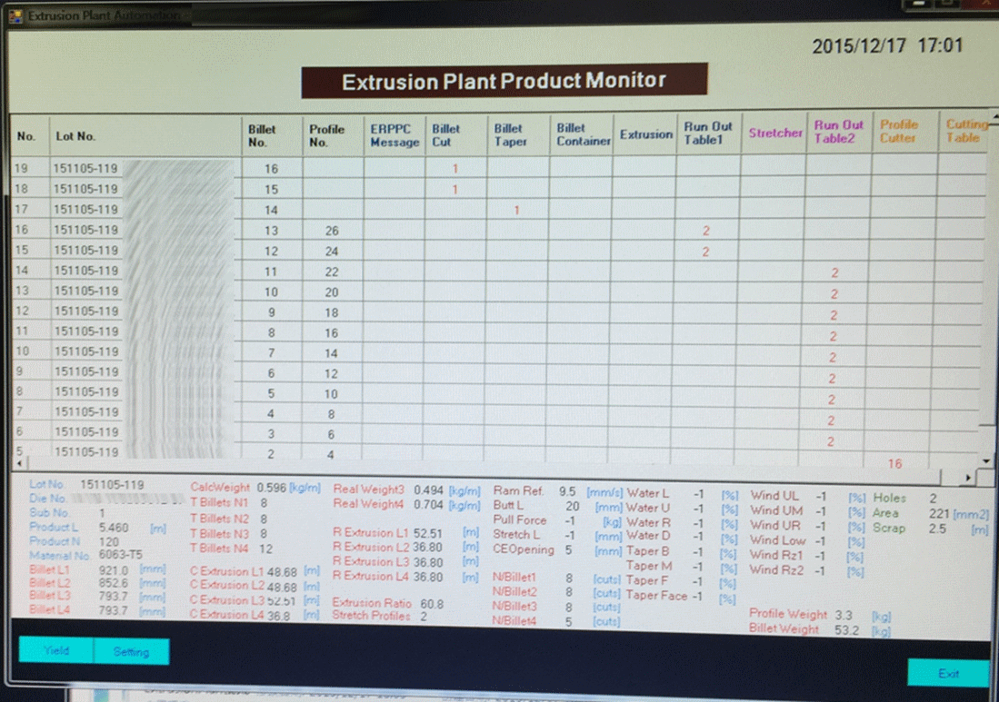
図1-2> アルミ押出工場の自動化の例
・押出形材切断で製品が16個できた履歴があるEPの画面。
・長尺ビレット、ビレット、押出形材、製品になるまでの過程をモニタし、各機械に自動でパラメータをセットします。
・ストレッチが終了した押出形材2×9=18本が、切断を待っています。
・2個の押出形材の切断で、2×8=16個の製品ができました。1個の押出形材を8分割したのが分かります。
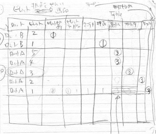
図1-3>EPのモニタ画面の手書きのメモ。
・中国のダリマクドナルド店で、コーヒーを飲みながら、このメモ作りました。工場の作業者がそれに非常に興味を持ちました。このアイデアのおかげで、EPができました。
・図1-1に説明したように、各工程でロットが異なることがあります。
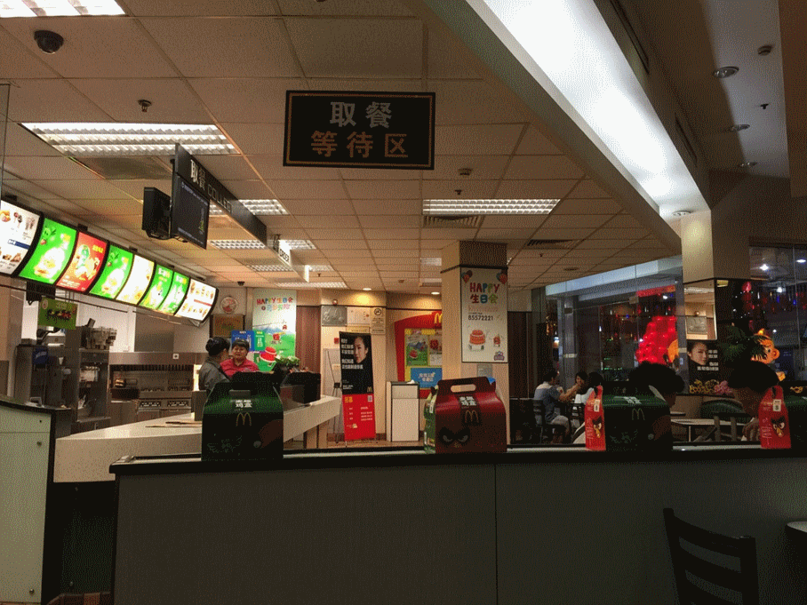
図1-4>ダリのマクドナルド店で、EPのモニタ画面をデザインしました。
・マクドナルド店は、映画館などがあるダリ商店街の入り口にあります。秋葉原のような電子部品を販売している区画もあります。出口にはケンタッキーフライドチキンがありました。
・チーズバーガーセット料金は400円ぐらいで、日本と比べて、少し安いかもしれません。支払はカード払いで中国光大銀行のUnionPayを使用していました。UnionPay用の端末が料金を支払うところに置いてありました。
・UnionPayは中国で預入して、日本のコンビニ店のATMで引き出しができます。

図1-5>マクドナルド店の前の噴水。ダリ商店街の入り口です。

図1-6>マクドナルド店の前の噴水とクリスマスツリー。
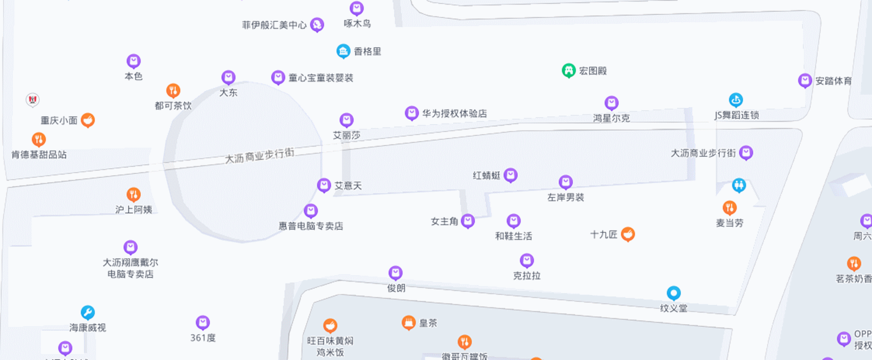
図1-7>マクドナルド店があるダリ商店街の地図。
・麦当劳は中国語でマクドナルドの意味です。肯德基はケンタッキーです。
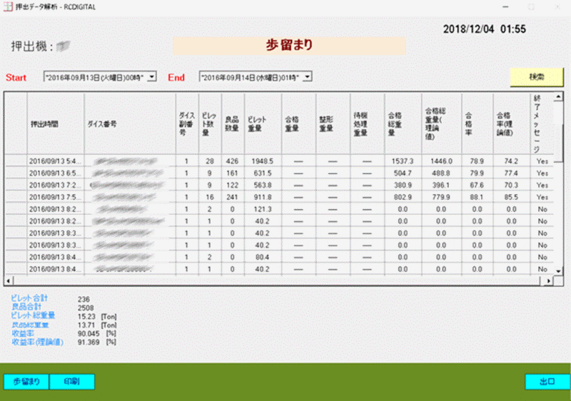
図1-8>金型毎にロットの歩留まりをリアルタイムに表示します。
↑TOP of Page
2
産業用ETHERNETとは
オフィスのLANはパソコンによるLANです。工場のLANは、リアルタイム通信機能があるPLCによるLANです。そのため、PLCメーカー毎に異なった通信プロトコル、異なったケーブルが使用されていました。
例えば、オムロンのController Link, シーメンスのProfibus DPなどです。
EtherCATやCC Link IE Fieldは、パソコンLANと同じケーブルですが、SWITCHINGハブは、パソコンとは別になります。TCP/IPも使用できません。
PROFINET 、Ethernet/IP、Modbus/TCP, CC LINK IE TSN、MECHATROLINK-4、Sercos、FL-netは、工場のLAN用のプロトコルですが、パソコンのSWITCHINGハブが使用できます。ケーブルはRJ45でパソコンと同じです。
Ethernetベースで、パソコンのLANとして使用できかつ、工場のLANの機能を持ったプロトコルを産業用Ethernetと呼びます。
産業Ethernetを使用すれば、事務所のLANと工場のLANをハード(ケーブル、ハブ、機器など)で区別する必要がなくなります。
ただし、ソフト(セキュリティや安全性、データ量の考慮、メンテナンス方法、ネットワークなど)の観点からは、検討が必要です。
一般に、工場に産業用Ethernetを導入することにより以下のメリットがあります。
・1本のLANケーブルで複数の機器の信号または1個の機器内にある複数のデータにアクセスできる。
・A/D変換、D/A変換が不要となるため、正確に信号を伝達できる。
・中継盤、配線コストの節約。
・システム変更、機器の増設が容易。
・機器データの通信、機器の校正、故障信号が送れる。
・ping等で稼働機器をチェック、LLDP/SNMPなどのコマンドで機器状態を報告・モニタできる。
2.1 代表的な産業用ETHERNETの比較
| 項目 |
PROFINET |
CC Link IE TSN
|
備考
|
|
仕様の公開
|
2001年にPROFINET CBA
2003年にはPROFINET IO
2019年にはTSN(Time Sensitive Networking)が仕様に含まれ、コンフォーマンスクラスDに分類さた。
|
2007年にCC Link IEの仕様が公開、
2018年にCC Link IEの次世代ネットワークとしてCC Link IE TSNの仕様が公開される。
|
|
|
通信速度
|
100Mbps
オプション1Gbps
|
1Gbps/100Mbps
|
|
| |
通信媒体
|
100BASE-TX
オプション:1000BASE-Tなど
|
IEEE 8023 1 OOOBASE-T 規定ケ - プル(カテゴリ 5e 以上)、
IEEE 802.3 1 OOBASE-TX 規定ケープル(カテゴリ 5 以上)、
R J -45 コネクタ、 M1 2 コネクタ
|
|
|
1局あたりの最大サイクリックサイズ
|
PROFINET IO
256バイト
|
各局、入出力合計で最大4G(4,294,967,296)バイト。
|
比較できない。
|
|
トランジェント伝送
|
S7 Communication
160バイト
TCP/IP
S7-1500:64kバイト
|
2048バイト。
各局サーバ機能、クライアント機能あり
伝送容量はSLMPと同一。
|
|
|
通信方式
|
NRT,RT,IRTがある。
NRT: TCP/IPをベースとした通信。
RT: Ethernetフレーム内のVLANタグ(IEEE803.1Q)で優先度を定義する。
IRT: 通信をサイクルに分け、1サイクルの中でリアルタイムデータと非リアルタイムデータの時分割を行なう。専用ASICを使用する。
TSN: 対応予定。
|
時分割方式
|
CC Link IE TSN だけでなく、PROFINETもIEC/IEEE60802のTSNを対応予定。
|
|
Synchronization function
|
RT,
IRT
|
IEEE802.1AS,
And IEEE 1588 v2 compliant
|
|
|
1ネットワークの接続ノード数
|
制限なし
|
64,770台(マスタ局とデバイス局の合計)
|
|
|
最大ノード間距離
|
100メートル以内
|
・ツイストペアケーブル(IEEE 802.3準拠)の場合:100 m
・光ファイバ(IEEE 802.3準拠マルチモードファイバ)の場合:550 m
・光ファイバ(SI-POF)の場合:20 m
・光ファイバ(SI-HPCF)の場合:100 m
|
|
|
最大分岐数
|
―――
|
上限なし
|
|
|
トポロジー
|
ライン、リング、スター、ツリー
|
ライン、スター、ライン・スター混在、リング、リング・スター混在、メッシュ
|
|
|
伝送ケーブル
|
銅線、光ファイバ、無線
|
銅線、光ファイバ、無線
|
|
|
マスタとデバイスの通信
|
1:1
複数マスタ可能。
|
1:多
複数の通信周期運用が可能。
|
|
|
実装方法
|
ハード(IRT)とソフト(NRT,RT)の両方が可能。
|
ハードとソフトの両方が可能。
|
|
|
SNMP対応 |
〇
|
〇
|
|
|
カプラーソリューション
|
お互いカプラーを経由して通信できる。
|
お互いカプラーを経由して通信できる。
|
CC Link 協会とPIの連携。
|
|
コンパニオン仕様
|
―――
|
2017年にCSP+のコンパニオン仕様をリリース。
|
CC Link協会とOPC Foundationの連携。
|
↑TOP of Page
3
Profinetとは
PROFINETは産業用Ethernetの一つです。
1980年代に作られたPROFIBUSの後継として、2001年にPROFINET CBAの仕様が公開されました。2003年にはPROFINET IOの仕様が公開されました。2019年にはTSN(Time Sensitive Networking)が仕様に含まれ、コンフォーマンスクラスDに分類されました。
PROFIBUSとPROFINETはPI(PROFIBUS & PROFINET International )(日本の場合は、日本プロファイバス協会)によって、技術開発、技術サポート、製品の認証、トレーニングが行われています。
3.1 PROFINETの特徴
| Item |
Contents
|
PROFIBUS
|
|
通信
|
NRT
(Non Real-time)
|
・TCP/IPをベースとした通信。
・リアルタイム性を要求されないアプリケーション。例>ユニット間通信、またはパラメータ通信。
・約100msecのサイクルタイム。
・データサイズは最大1500バイト。
|
・PROFIBUS DP
は、数msec以下のサイクルタイム。
・最大12Mbps。
・データサイズは、最大244バイト。
・ハイブリッド方式(マスタ・スレイブ方式とトークン・パッシング方式の組み合わせ)
・ケーブルはRJ45ではなくRS485。図4-2。
|
| RT(Real-time)
| ・標準のEthernetハードウェア上にソフトプロトコルを追加し、4~10msec程度の周期で通信するリアルタイム通信を実現。
・Ethernetフレーム内のVLANタグ(IEEE803.1Q)で優先度を定義することでRTのフレームは、非リアルタイムデータ(NRTまたはTCP/IP等)より、高い優先度で処理される。
・RTは、現在のフィールドバスとほぼ同等のパフォーマンスを提供。
・デフォルトはRT。
|
| IRT (Isochronous Real-time)
| ・ある通信時間内に必ず通信が実行されること(Deterministic性)をRTより高いレベルで保証する。
・通信の周期は最速31.25μsec、ジッタ(揺らぎ)は1μsec以下。
・IRTはモーションコントロールのような厳しい実時間性が要求されるアプリケーションに使われる。
・通信のハードウェアとして、スイッチ機能内蔵の専用ASICを使用する。図4-1参照。
・Ethernetの通信帯域を分割してリアルタイム性を保証。
|
|
制御アプロケーション
|
|
・PROFIBUSで行っていたリアルタイム処理(PLCと現場機器の通信、アラームなど)ができる。
・PROFIBUSと同様に、GSDファイルで、現場機器と接続できる。
・プロキシまたはゲートウェイの技術を使って、フィ ー ル ド バ ス 機器を容易にか つ シ ー ム レ ス に
PROFINET システムに統合できる。例えば、PROFIBUS、Interbus。
|
GSDファイル。
|
|
モーションコントロールでの同期制御
|
|
・IRT通信を使うことで、EthernetのTCP/IP通信と、モーションコントロールの同期制御が同時にできる。
・IRT通信では、例えば、1msecの周期時間の中でリアルタイムデータと非リアルタイムデータの時分割を行う。この帯域分割は、PROFINET IRT機能を搭載するASICで実行されるので、Ethernet上のネットワーク機器にリアルタイム性を依存しない。
・Fast Forwarding, Dynamic Frame Packing, Frangmentationといった技術を使って、周期時間を最大31.25μsecまで早くすることができる。
・PROFIdriveプロファイルを用意して、異なる会社で提供する回転機器(インバータ、サーボドライブ)のインタフェースを共通化する。
|
PROFIdrive.
|
|
安全アプリケーション
|
|
・リレー装置を仕様しないで、PLCでシャットダウンシステムを構成。
・PROFIsafeプロファイルを使用して、標準の制御通信と安全通信を1本のバスで行うことができる。
|
PROFIsafe.
|
|
エネルギー管理
|
|
・PROFIenergyプロファイルにより、生産活動が停止している時は(日曜日など)、現場機器にOFFを指令する。
|
|
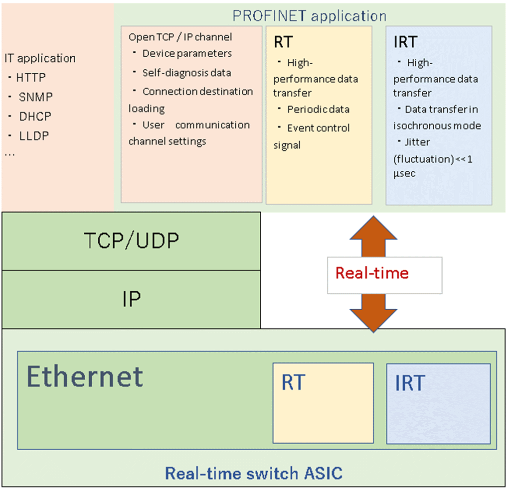
図3-1>IRTノード内のNRT、RT,IRT。将来は、ここにTSNが追加される。
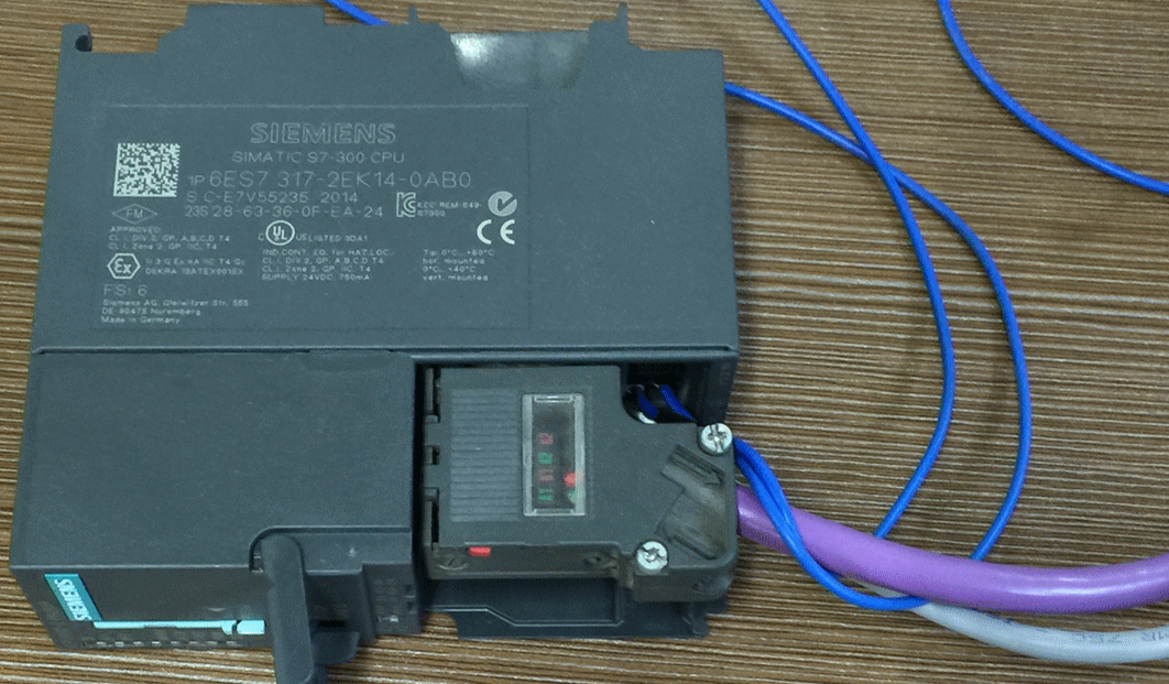
図3-2>紫がRS485のPROFIBUS DPケーブル,灰色がRJ45のEthernetケーブル。
参考資料>
日本プロフィバス協会 (profibus.jp)
↑TOP of Page
4
TIA Portalとは
2010年に、βバージョンとしてTIA PortalはV10として初めて紹介されました。
この時に、PLCのプログラム作成ツールSTEP7とタッチパネルの画面作成ツールWinCCが、1つのツールTIA Portalで使用できるようになりました。
単独で使用するSTEP7は、2010年のときのバージョンがV5.5です。STEP7は、2021年にはバージョンはV5.7になりました。
TIA Portalの現在の最新バージョンはV17です。
TIA Portalは、1つのプロジェクトで、工場のPROFINETのLAN上で稼働するPLCプログラムとタッチパネル(HMI)プログラムを開発、デバッグ、メンテナンスできる工場のLANシステムの開発ツールです。
パソコンのツールのVisual Studioを例にとれば、HIMIがForm、PLCプログラムがDLLプログラム、DBがクラスのプロパティ、FCとFBがメソッド、通信はイベントと対応します。
工場のLANのシステムが、1つのTIA Portalのプロジェクトになります。
GX Works2では、1つのプロジェクトでは1つのPLCしか開発できません。GT Desiner3も1つのプロジェクトでは、1つのHMIしか開発できません。PLCとHMIでは、開発ツールも異なっています。
TIA Portalは、1つのプロジェクトで複数のPLCとHMIを開発できるので、ネットワークプログラミングが容易になります。ネットワークプログラミンが必要なければ、GX Works2とGT Desiner3でもよいですが、工場の自動化には、複数のPLCと複数のタッチパネルのネットワークプログラミング必要になります。
(GX Works2でCC Link IEを使用する時は、マスタPLCを指定して、PLC毎に、送受信エリアを指定すれば、PLC毎のデータの送受信はできるようになっています。)
PLC to PLCの手段には、いろいろな方法がありますが、S7 Communications でデータの送受信をするのが、一番簡単です。PROFINETだけでなく、PROFIBUS DPでも使用可能です。
PLCとHMIだと、プログラミングは不要で、さらに簡単になります。
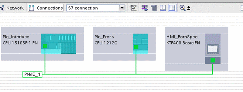
図5-1>デバイス接続の方法は、接続方法を指定して、デバイスとデバイスをマウスで直結します。
PLC或いはタッチパネルでデータを送受信するためのメモリはDB(Data Block)という名前です。パソコンでネットワークのプログラムを作成する場合もDB(Data Base)をよく使用します。たまたま、略称のDBが同じなので、勘違いするかもしれません。DBは、データエリアの部品化と呼ばれています。
構造化プログラミング、変数プログラミングの機能もあります。
ネットワーク以外にも以下の機能があります。
・国際規格の PLCプログラミング 5 言語をすべて標準搭載(LD,FBD,ST,SFC、IL)。
・モーションコントロールの標準ライブラリ“Library Motion Control SINAMICS“搭載。

説明>「1:n」、「Cam」、「Pos」「Flying Saw」、「Cross-cutter」、「Winder」、「Line Tension Control」、「Traversing Drive」が、標準ライブラリでサポートされています。
・オートチューニング付きPIDコントローラー命令。
・PLCシミュレータ。
オプションには以下があります。
・安全PLCソフトウェア。
・バーチャルコントローラ。
・TIAポータルマルチユーザーエンジニアリング。
・TIAポータルオープネス。
・TIAポータルクラウドコネクター。
・SIMATIC Visualization Architect – SiVArc。
・HMI パネル編集ソフトウェア WinCC(Basicパネル以外で必要)。
・インバータ、サーボドライブパラメータ編集ソフトStartdrive。
↑TOP of Page
5
OPC UAサーバーと工場PLC
OPC UA サーバーPLCと工場PLCのデータ交換には、各PLCにDB(Data Block)を作成します。通信の方法には、S7 Communications、Modbus/TCP、Open User communications、I-Device、OPC UA、Flexible F-Linkなどがあります。
S7 Communicationsが一番簡単です。通信の必要性に応じて、他の方法を選択することになると思います。
Industry Support Siemens
に行けば、TIA Portalのサンプルが沢山あります。どの方法を選んでも問題ないと思います。
OPC UA クライアントからのデータを受信する ReciveOpcDBとOPC UAクライアントにデータを送信するSendOpcDBが必要です。
工場のLANのPLCとHMIからデータを受信するReceivServerDBと工場の他のPLCにデータを送信するSendServerDBが必要です。
工場のLANのPLCには、OPC UA Serverからデータを受信するReceivePlcDBとOPC UA Serverにデータを送信するSendPlcDBが必要です。
HMIにはDBはいりませんが、HMI tag と DBの中の変数の紐づけが必要です。
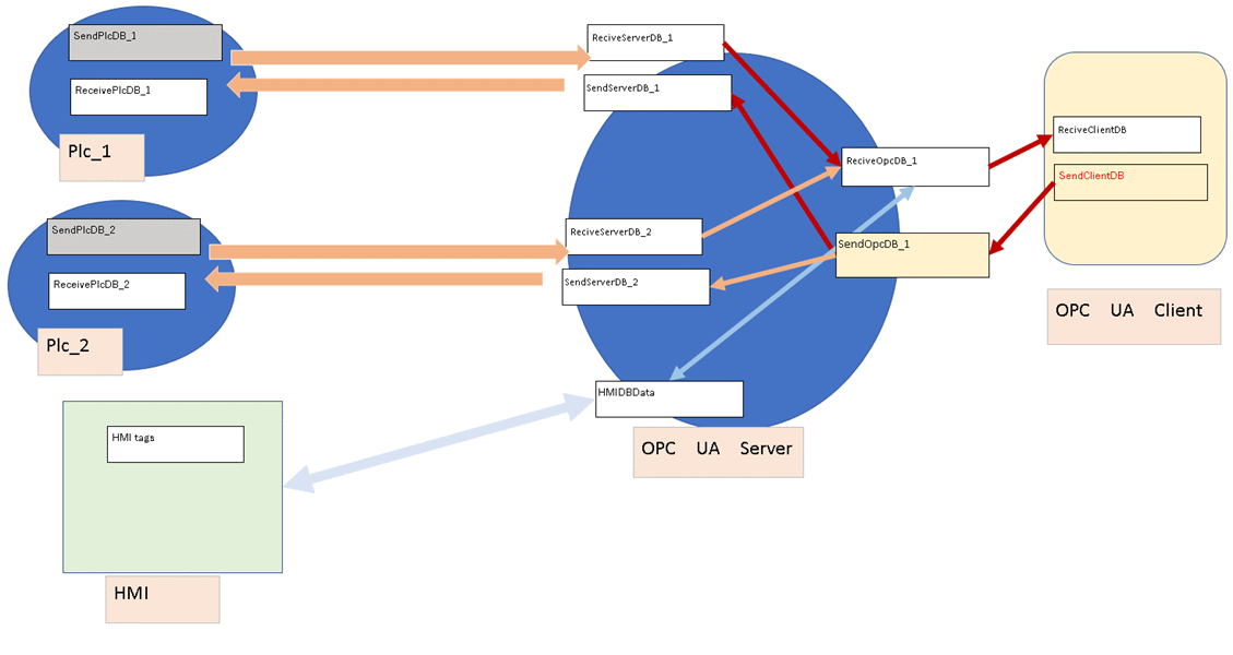
5-1>OPC UA Server PLCと工場のLAN上のPLC、HMIとのインターフェイス図
5.1 主な通信プロトコル
5.1.1 S7 Communications
利点
•片方のPLCだけでプログラムミングが必要。
•すべてのSimaticPLCで動作。
•通信メディアから独立。
•すべてのS7データ領域で使用できる。
•TIA PortalではWizardが使用可能。
短所
•セキュリティなし。
•S7-1200およびS7-1500ではデフォルトでブロックされてる。
•データブロックの最適化は不可。
•転送できるデータは160バイト未満。
•転送の確認は必要ありません。
•常に接続リソースを使用します。
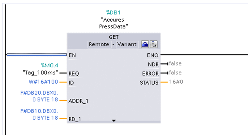
図5-2>SFB(System Function Block)のGET。
OPC UA ServerのPLCで実行して、各機械のデータを取得できます。
| Parameter |
Declaration |
Data type
|
Description
|
|
REQ
|
Input
|
BOOL
|
ポジティブエッジでデータ交換する。 |
|
ID
|
Input
|
WORD
|
パートナーCPUへの接続を指定するためのアドレス指定パラメーター。 |
|
NDR
|
Output
|
BOOL
|
ステータスパラメータNDR:
0:ジョブはまだ開始されていないか、まだ実行中です。
1:ジョブは正常に完了しました。
|
|
ERROR
|
Output
|
BOOL
|
ステータスパラメータのERRORおよびSTATUS、
エラーコード:ERROR = 0の時、
STATUSの値は次のとおりです。
0000H:警告でもエラーでもない
<> 0000H:警告で、STATUSは詳細情報を提供します。
エラーコード:ERROR = 1の時、
エラーが発生しました。 STATUSは、エラーのタイプに関する詳細情報を提供します。
|
|
STATUS
|
Output
|
WORD
|
|
ADDR_1
,2,3,4
|
Input
|
REMOTE
|
読み取られるパートナーCPU上の領域へのポインター。
REMOTEポインターがDBにアクセスするときは、常にDBを指定する必要があります。
例:P#DB20.DBX0.0 BYTE 10
|
|
RD_1
|
Input
|
VARIANT
|
読み取ったデータが入力されるローカルCPU上の領域へのポインタ。
ローカルの場合はDB名も指定できる。 |
5.1.1.2 表5-1>GETのパラメータと出力。
5.1.2 Modbus/TCP
利点
•ベンダー間のコミュニケーション。
•組み込みの診断。
•イーサネット経由でルーティング可能。
•最適化されたデータブロックがサポート。
•定義された通信タイムアウト。
短所
•セキュリティや暗号化は不可。
•サーバー/クライアントブロックはプログラミングが必要。
5.1.3 Open User Communications
5.1.3.1 Without security
Advantages
・ Cross vendor open communication.
・ Built in diagnostic if using TCPIP.
・ Routable over Ethernet.
・ Optimized Data blocks are supported.
・ Setup Wizard.
・ Safety certified communication possible.
・ Security and encryption supported.
Disadvantages
・ Send/Receive blocks must be programmed.
・ Broken TCPIP link takes time to error.
5.1.3.2 With security
Advantages
・ Same Blocks as Unsecure.
・ Can be added at a later date.
・ TCON_IP_V4_SEC is used for secure communication.
・ Definitely signed and can be encrypted.
Complexity
・ Certificate handling must be implemented.
・ Use of certificates may mean that you need to protect the
project using the certificate manager.
Disadvantages
・ Can be harder to fault find during initial setup.
・ Cannot use Wizard for security setup.
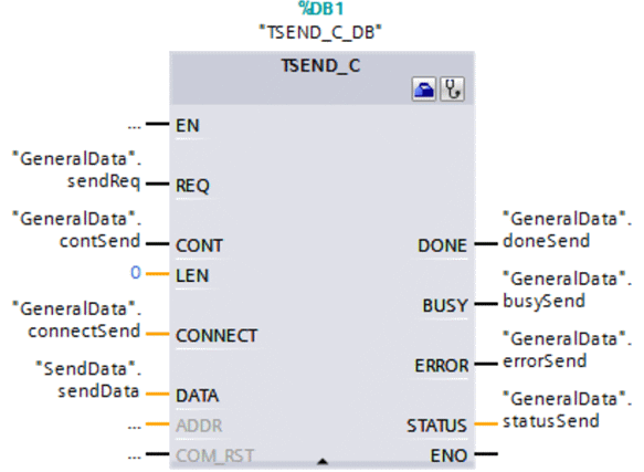
5.1.3.1 図5-3>SFB(System Function Block)のTSEND_C
各機械のPLCがOPC UA Serverにデータを送信する。OPC UA Serverは、SFBのTRCV_Cを実行してデータを受信します。
| Parameter |
Data type |
Variable
|
Description
|
|
REQ
|
BOOL
|
"GeneralData".sendReq
|
立ち上がりエッジで送信ジョブを開始します。 |
|
CONT
|
BOOL
|
"GeneralData".contSend
注>表5-3参照。
|
通信接続を制御します
0:通信を切断します。
1:通信接続を確立し、通信接続を維持します。
CONT = 1の場合、TSEND_C命令は次のように構成します。
通信接続を確立します。
接続が構成されたら、それは自動的に維持および監視されます。
|
|
LEN
|
UINT
|
0
|
ジョブとともに送信できるバイト数。 |
|
CONNECT
|
VARIANT
|
"GeneralData".connectSend |
接続パラメータの構造体へのポインター:
・ ISO-on-TCPの場合、TCON_IP_RFCシステムデータ型を使用します。
・ TCPの場合、TCON_IP_V4システムシステムデータ型を使用します。
|
|
DATA
|
VARIANT
|
“SendData”.sendData |
送信するデータのアドレスと長さを含む送信領域へのポインター。 |
|
DONE
|
BOOL
|
"GeneralData".doneSend |
0か1のステータスパラメータ
0:ジョブはまだ開始されていないか、まだ実行されています。
1:ジョブはエラーなしで実行されました。
|
|
BUSY
|
BOOL
|
"GeneralData".busySend |
0か1のステータスパラメータ
0:ジョブはまだ開始されていないか、すでに終了しています。
1:ジョブはまだ終了していません。 新しいジョブを開始できません。
|
|
ERROR
|
BOOL
|
"GeneralData".errorSend |
0か1ののステータスパラメータ:
0:エラーなし
1:エラーが発生しました。
|
|
STATUS
|
WORD
|
"GeneralData".statusSend |
命令のステータス。 |
Table 5-2> T_SEND_C parameters and outputs.
| Byte |
Parameter |
Data type |
Value |
Description |
| 0 and 1 |
InterfaceId
|
HW_ANY |
64 |
CPUの統合PROFINETインターフェースのハードウェア識別子。 |
| 2 and 3
|
ID
|
CONN_OUC |
1 |
この接続への参照(値の範囲:1〜4095)。
IDの下のTSEND_CおよびTRCV_C命令には、このパラメーターの値を指定する必要があります。 |
| 4
|
ConnectionType
|
BYTE |
16#0B |
接続タイプ:
・11:TCP
(16#0B hex = 11 dez)
・19:UDP
(16#13 hex = 19 dez)
|
| 5
|
ActiveEstablished
|
BOOL |
False |
接続確立のタイプの識別子:
・false:パッシブ接続の確立。
・true:アクティブな接続の確立。
|
| 6 to 9
|
RemoteAddress
|
ARRAY [1..4] of BYTE |
- |
パートナーエンドポイントのIPアドレス。例>192.168.0.3
・addr [1] = 192
・addr [2] = 168
・addr [3] = 0
・addr [4] = 3
|
| 10 and
11
|
RemotePort |
UINT |
2000
|
リモート接続パートナーのポートアドレス(値の範囲:1〜49151)
|
| 12 and
13 |
LocalPort
|
UINT |
2000 |
ローカル接続パートナーのポートアドレス(値の範囲:1〜49151) |
Table 5-3> TCON_IP_V4 structure, one of the parameters of "GeneralData" .connectSend
5.1.4 I-Device
利点
•非常に高速なデータ通信(RT / IRT)。
•組み込みの診断。
•ハードウェアのセットアップのみソフトウェアなし。
•安全認証通信。
•サードパーティシステムへの統合が可能。
短所
•PN/PNカプラーを使用しない限りルーティングできません。
•セキュリティなし。
•実際の入力/出力リソースを使用します。
5.1.5 OPC UA
利点
•ベンダー間のオープンコミュニケーション。
•組み込みの診断。
•イーサネット経由でルーティング可能。
•最適化されたデータブロックがサポートされています。
•サーバーにソフトウェアは必要ありません。
•コンパニオン仕様をサポート。
•セキュリティと暗号化がサポートされています。
Disadvantages
•デフォルトでは、サーバーオプションをオンにすると、以下が許可されます。
PLCにアクセスし、それを参照して何が可能であるかを見つけることができる。
5.1.6 Flexible F-Link
利点
•1200/1500PLCでサポート。
•イーサネット経由でルーティング可能。
•専用の安全通信。
参考資料>
Siemens DI FA Stay in Touch Webinar Slides
↑TOP of Page
6
GSDファイルとは
PLCとタッチパネル以外の機器、例えばモータ―のドライバ、ロボットのコントローラ、をTIA PORTALのネットワークビューに表示するには、PROFIBUSではGSDファイル、PROFINETではGSDMLファイルが必要です。
これは、機器のメーカーが提供します。そのファイルによって、通信設定などを行います。
PROFINETの場合は、XMLファイルになっているので、GSDML( General Station Description Markup Language)と呼ばれます。
GSDML ファイルを、プロジェクトにインストールするには、以下の処理を行います。
1. [Options]メニューで、[Install device master data files]コマンドを選択します。
2. [Install device master data files]ダイアログボックスで、GSDMLファイルを保存するフォルダーを選択します。
3.表示されたGSDおよびGSDMLファイルのリストから1つ以上のファイルを選択します。
4.[ Install]ボタンをクリックします。
5.インストール用のログファイルを作成するには、[Save log file]ボタンをクリックします。
例1>
安川電機のロボットコントローラをTIA PORTALのネットワークビューに表示します。
GSDファイルは、GSDML-V2.3-HMS_CUSTOM-ABSPRT-20170815.xmlです。

図6-1>ネットワークビューにロボットコントローラを表示する。

図6-2>登録されているGSDファイル。
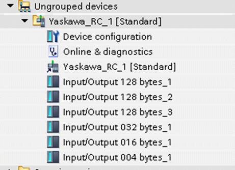
図6-3>Project treeで、ロボットコントローラは、Ungrouped devicesに表示されます
| Component |
Quantity |
Note |
| YRCI 000micro with firmware 2.31.00
|
1
|
Rototcont controller |
| MotoMINI
|
1
|
Robot arm |
| YASUKAWA MotoLogix
|
1
|
Version: 1.2.4 |
| YASUKAWA GSD file for YRC 1000micro with firmware 2.31.00
|
1
|
Version:gsdml-v2.3-hms_custom-absprt-20170815.xml |
Table 6-1> Robot controller components
Example 2>
Motor speed control with Semense motor driver SINAMICS G120X
The GSD file is GSDML-V2.34-Siemens-Sinamics_G120X-20180814.xml.
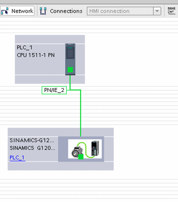
図6-4>ネットワークビューにモータドライバを表示する。

図6-5>登録されているGSDファイル。

図6-6>Project treeで、モータドライバは、Ungrouped devicesに表示されます。
| Component |
Quantity |
Note |
| SIMATIC S7-1215C
DC/DC/DC (FW 4.2.1)
|
1
|
他のタイプのSIMATICS7-1200またはS7-1500PLCを使用できます。 |
| SINAMICS G120X
FSA (FW1.0.1) with IOP-2
|
1
|
PROFINETインターフェースを備えた他のタイプのSINAMICSG120Xを使用できます! |
| Smart Access Module
(optional use)
|
1
|
SAMの使用はオプションです。
IOP-2は、G120Xの試運転にも使用できます。
|
SIMATIC STEP7
Professional – WinCC
Advanced V15.1 Upd 2
|
1
|
他のバージョンのTIAポータル(下位または上位)を使用して、説明されているように構成を行うことができます。
注>サンプルプロジェクトを開くことができるのは、V15.1以降のみです。
|
| SINAMICS G120X
GSDML file
|
1
|
GSDMLファイルは、PLCとTIAポータルのドライブ間の通信構成に使用されます。 |
Table 6-2> Motor Driver Hardware and Software Components
Reference material>
SIMATIC Robot Integrator for YASKAWA - Getting Started - ID: 109772216 - Industry Support Siemens
Speed Control of SINAMICS G120X with SIMATIC - ID: 109772227 - Industry Support Siemens
↑TOP of Page
7
RcdWinのタッチパネル対応
押出速度の設定のために、OPC UAサーバーのET200SPとタッチパネル(SIMATIC HMI KTP400 Basic)をPROFINETで接続しました。図7-1。
押出速度の設定はEMを使用してパソコンからでもできます。図7-2。タッチパネルは大きさが小さいので、場所の制約が少なくなります。キーボードやマウスが苦手な人には使いやすくなるかもしれません。
2か所から押出速度を入力できるようにする時に注意することがあります。ダイヤル式の押出速度設定器を使用すると、リモートと現場を区別する信号が必要になることです。タッチパネルで押出速度を設定する時は必要ありません。
図7-1は、RcdWinのタッチパネル対応です。
図7-2は、RcdWinとEMです。
図7-3は、RcdWin、EM、EDA、OPC UA server、プレス PLC、タッチパネルを接続したネットワーク図です。
図7-4は、RcdWin,タッチパネル、Press PLCのネットワークに、OPC UAとS7 Communicationを使用した場合のデータの流れです。
TIA Portalは、ネットワークのデータに構造体やDB(Data Block)を使用できます。そのため、データの流れをシンプルな図で表現できます。
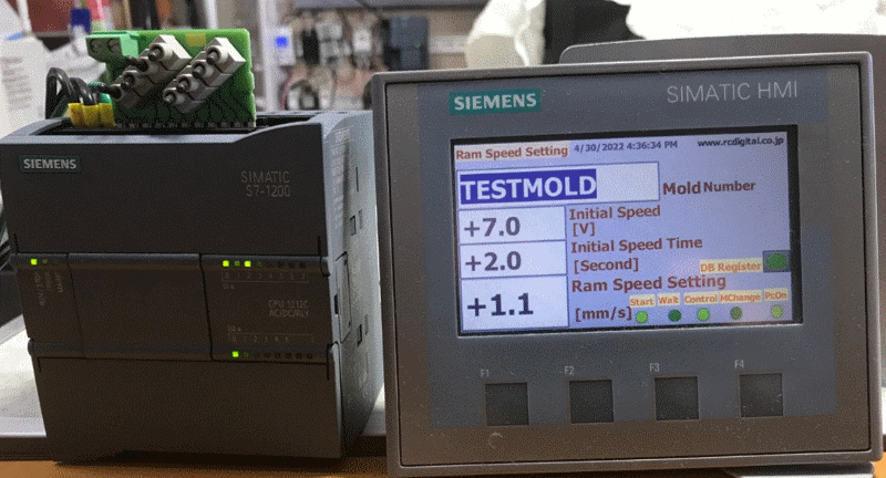
図7-1>RcdWinのタッチパネル対応
左側のPLCは、S7-1200 1212 AC/DC/RLYです。ネットワークのテストをするために、押出機のPLCを模擬しています。AC/DC/RLYの意味は、
AC: 電源がAC
DC: 24V DC Inputs 0.5 amp Max/channel、
RLY: relay outputs, 5-30V DC或いは 5-250V AC, 2 amps Max/channel。
PLCの上部のディップスイッチは、24V DC Inputsです。左側の0番目と2番目がONになっています。
RLYのOutputsは、relay outputs の0番がONになると、最下段のLEDの0番がONになります。PLCの稼働中の意味です。
奥の制御盤にあるのが、ET200SP OPC UA serverです。
S7-1200の右側がタッチパネル(KTP400 Basic)です。StartとControlのランプがONになっています。
S7-1200のディップスイッチの0と2番のONに対応しています。PcOnは、パソコンのRcdWinのRUN状態です。
押出速度や金型はパソコンとタッチパネルで変更できます。ただし、パソコンと現場を区別する信号は必要ありません。
片方で設定した値は、もう片方に自動で送信されるからです。ダイヤル式の速度設定器具を使用すると信号が必要になります。
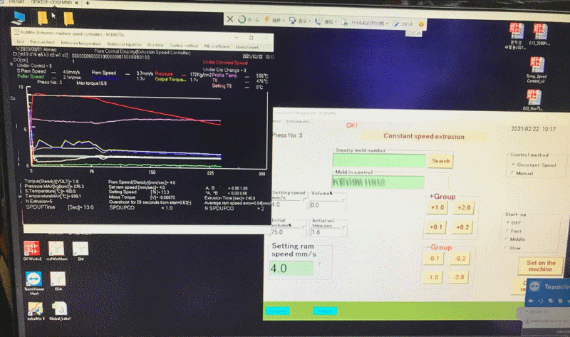
図7-2>RcdWinとEMによる等温押出
パソコンではRcdWinで押出状況のグラフのチェックとEMで押出設定速度の設定が同時にできます。
グラフの説明。
・ビレットテーパーを使用して、温度傾斜を付けたビレットで,等速押出と等温押出を同時に実行しています。ビレットテーパーを使用することにより、等温押出が簡単になりました。必要がある時だけ、微調整を行うことができます。
・圧力がリリーフ圧力を超えると、押出速度は殆ど上昇しません。そのため、制御電圧を下げて省エネルギーを実現しています。長時間の全負荷運転はサーマルリレーがONになります。製造が中断して製品不良になります。また、長時間の全負荷運転は、形材が飛び出して作業者が危険です。それらを防止します。多少、立ち上がりが遅くなるかもしれませんが、省エネ効果とトラブル防止で、結果的に生産性を向上します。
・図で分かるように、押出設定速度近辺で、動的に設定速度を微調整します。これは、オーバーシュートを防止です。押出設定速度の変更は、通常は作業者が行いますが、RcdWinは自動で行います。省人化になります。オーバーシュートを防止するために使用されているPIDパラメータの調整が必要なくなりました。
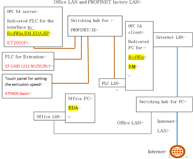
図7-3>RcdWin、EM、EDAとOPC UA server、Press PLC、タッチパネルを接続したネットワーク図
RcdWinとEMとEDAとタッチパネルを使用した場合の、典型的なネットワーク図です。PROFINETを使用することにより、オフィスと工場のLANに同じケーブルを使用できるようになりました。単純化することにより、メンテナンス性が向上します。
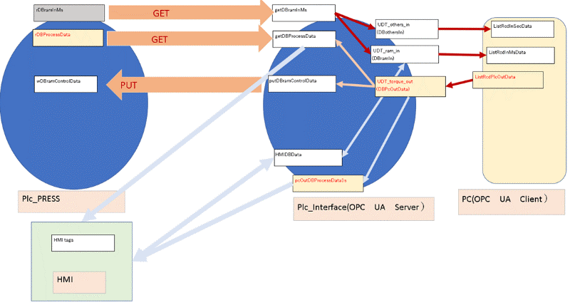
図7-4> RcdWin,タッチパネル、Press PLCのネットワークに、OPC UAとS7 Communicationを使用した場合のデータの流れです
TIA Portalは、ネットワークのデータに構造体やDB(Data Block)を使用できます。そのため、データの流れをシンプルな図で表現できます。
↑TOP of Page